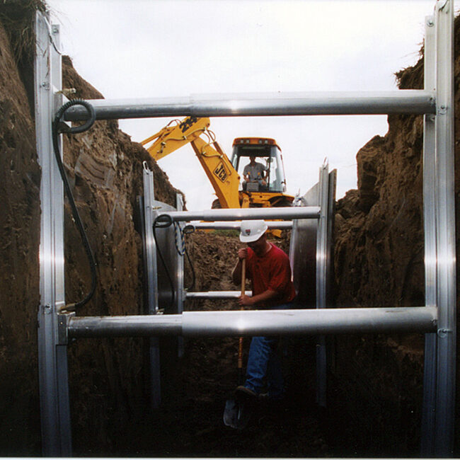
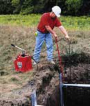
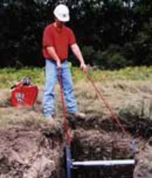
Designed to shore square, rectangular, and irregular shaped excavations, the Pro-Tec Equipment Manhole Braces bridge the gap between vertical hydraulic shoring and the Pro-Brace Hydraulic Framing system.
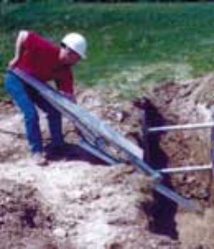
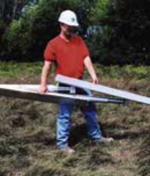
The Pro-Tec Equipment Manhole Braces create a clear, unobstructed working area, ideal for manhole and vault installations, as well as municipal work. The Manhole Braces can be easily transported to and from the job-site and are quickly assembled.
Features:
- Steel Box Tubing
- 4-Way hose bridle
- Lift eyes on all corners
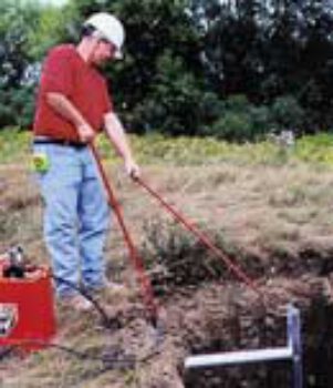
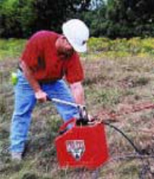
- Able to be pressurized with the Standard Pro-Tec Equipment Plastic Pump Can
- Certified by a Registered Professional Engineer
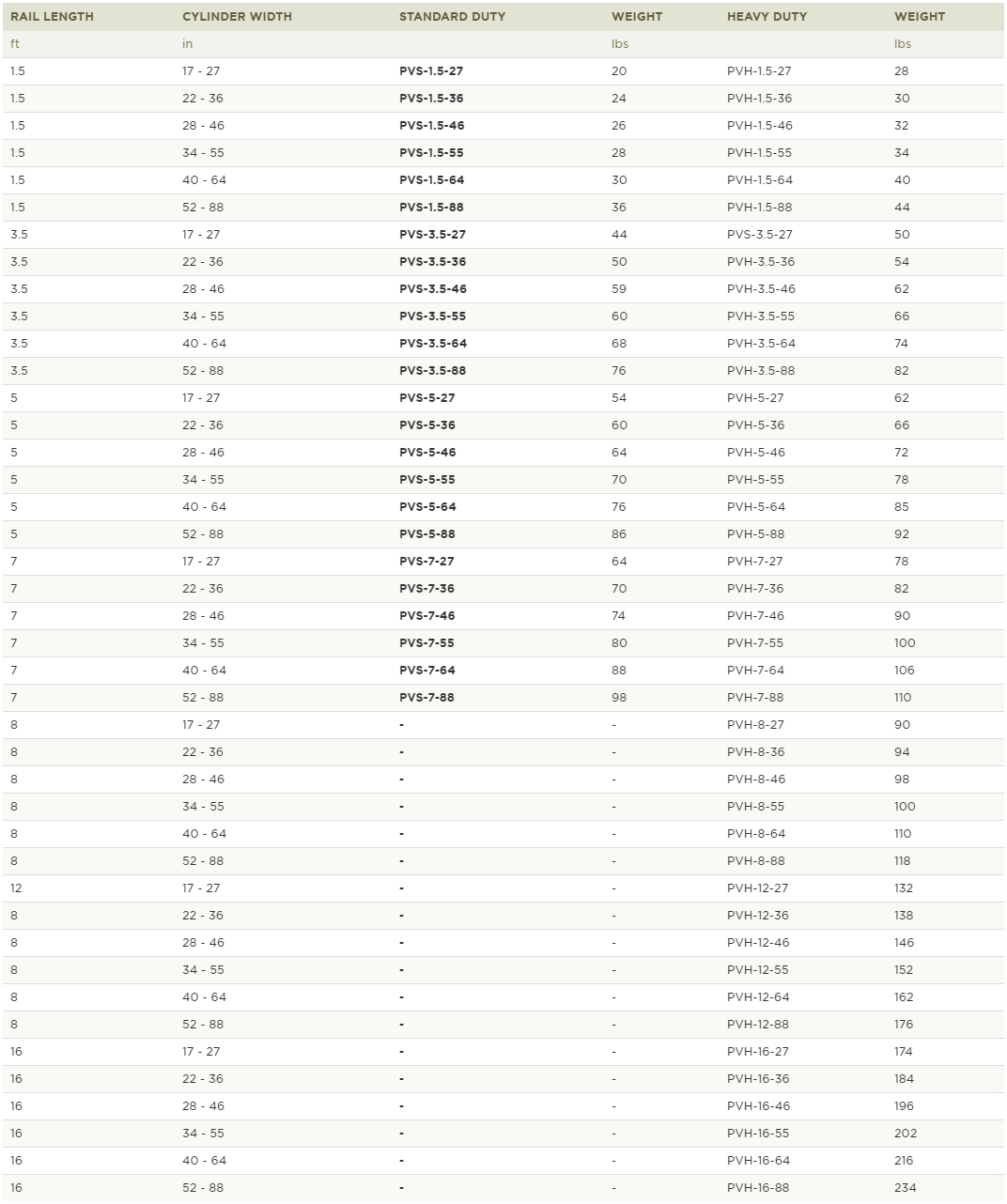
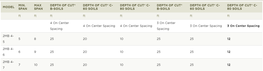
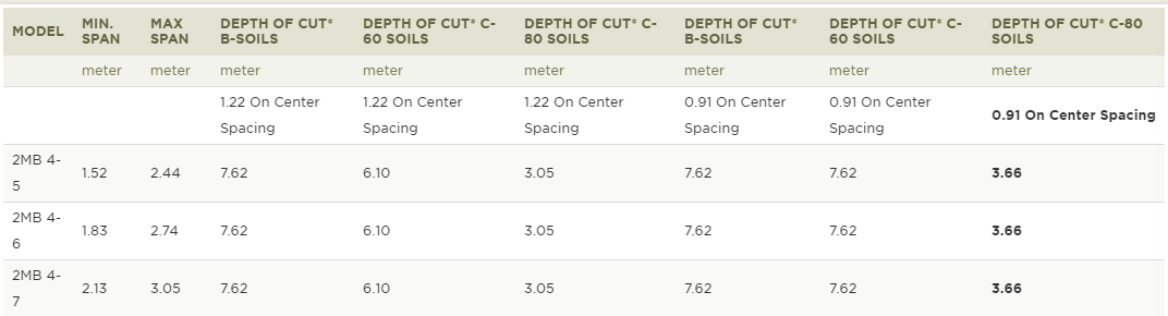
Manhole Brace Chart
*PSF (pounds per square foot) ratings indicate maximum shield capacities. Depths are based on B, C and C-80 soil types as described in OSHA’s 29 CFR Part 1926 Subpart P, October 31, 1989 with Type B not exceeding 45 PSF per foot of depth, Type C not exceeding 60 PSF per foot of depth and Type C-80 not exceeding 80 PSF per foot of depth. Determine actual soil pressure and consult manufacturers’ tabulated data prior to each use.
Job site photos are strictly intended for general product information only and may not comply with all applicable safety standards. Always refer to manufacturers’ serialized specific tabulated data, O.S.H.A. 29 CFR 1926 Subpart P for excavations and all applicable safety standards prior to each use